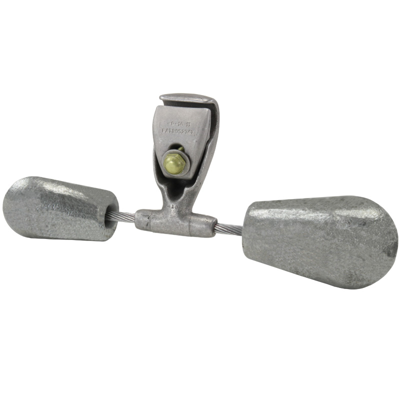
El nuevo amortiguador Dissipator 1700AA de alta eficiencia proporciona una mejora significativa en el rendimiento con respecto a nuestro amortiguador tradicional debido a su configuración única de peso en forma de campana. El nuevo diseño de peso compensado duplica el número de frecuencias resonantes, proporcionando así un rendimiento de eficiencia más consistente en el rango de frecuencias eólicas.
be6b811c28a649ffab097ada4ef2c59e
1700AA Series Asymmetrical Damper Test Data
1700AA Series Asymmetrical Dampers Scope This is a summary of design and testing for the new 1700AA asymmetrical series of stockbridge dampers being offered by AFL for overhead transmission lines. The 1700AA series is intended to be used as an equivalent to the current 1700 series of dampers. As shown below, the 1706AA, 1707AA and 1708AA asymmetrical configurations will be used in place of the previous 1706, 1707 and 1708 symmetrical sizes. Asymmetrical Damper (1700AA Series) Symmetrical Damper (1700 Series) Figure 1—Comparison of diameter ranges Background The stockbridge damper was invented in the early 1900s by George H. Stockbridge with Southern California Edison. The stockbridge damper patent was purchased from him in 1925 and began developing the damper and applying it to various conductors. AFL adapted the design over time to new transmission line industry requirements, resulting in the current 1700 series damper, the design of which has not changed significantly for over 30 years. It is known as the B-1700 series of damper and has an excellent reputation for being a solid design, widely used around the country and also used internationally.
Now AFL is again adapting to the needs of the utility market and is releasing a new series of damper, the 1700AA series. This damper, while different in some respects to the 1700 series, is essentially the same from a functional and design standpoint. The components are made from the same materials and the same method and location for assembly of the dampers is used (near Spartanburg, SC). The new damper design takes advantage of AFL’s already proven bell-shaped weight design, but is modified to take advantage of asymmetrical messenger cable lengths and differing weights in order to optimize the design further. By adjusting the lengths of messenger cable on either side of the damper and using differing weights on each side, the damper can now cover a wider frequency range with lighter components. But as with any new damper to be used on electric utility transmission lines, testing is very important. This document highlights three very important tests used to confirm the performance of a stockbridge damper: efficiency, fatigue and corona. Also included is a drawing for the 1700AA series. Design As noted, the design of the new 1700AA series is very similar to the already existing 1700 series. The basic components are shown below and the materials used are listed in the following table. Figure 2—1700AA Series Construction Component Materials COMPONENT MATERIAL FINISH Clamp Body and Keeper Aluminum Alloy Cast and finished Clamp Bolt Aluminum Alloy Anodized bolt head and lubricated threads Messenger Cable Steel Galvanized Damper Weights Cast Iron Hot-Dip Galvanized Damper Specifications by Size WEIGHT CONFIGURATION APPLICABLE DIAMETER RANGE (IN.) APPROXIMATE WEIGHT OF ASSEMBLY (LBS)* APPROXIMATE LENGTH OF ASSEMBLY (IN.)* 1706AA 0.971 - 1.210 9.3 15 1707AA 1.211 - 1.382 10.1 16 1708AA 1.383 - 1.825 17.6 19 * Weight and length may vary slightly according to clamp size used.
1700AA Series Asymmetrical Dampers Efficiency Testing General Dampers are required to dissipate the required amount of vibrational energy from overhead conductors. Several factors dictate the amount of required energy dissipation, including conductor tension, span length, geographic terrain and prevailing winds. Therefore, laboratory testing must be applied appropriately to field installations so as not to require more energy dissipation than the damper can provide. Test Setup A length of cable is attached at both ends to concrete abutments through the use of fittings and/or other hardware. The cable is tensioned to a value normally used in overhead transmission lines. The cable is then vibrated over a range of frequencies corresponding to what is expected to occur in field installations. During these vibrations, the power dissipated by the damper is measured by determining various amplitudes of vibration present in the vibrating cable. Theory and calculations for this type of test are listed in IEEE Std. 664, IEEE Guide on the Measurement of the Performance of Aeolian Vibration Dampers for Single Conductors. The results can be plotted in the form of damping efficiency, which gives a measure of the power dissipation of the damper (reference Figure 5, IEEE Std. 664). The tests listed here were all performed at one of AFL’s vibration spans located in Duncan, SC. Results Interpretation Dampers are matched to cables in large part by what is known as the cable’s characteristic impedance, or Z 0 . This impedance, which is dependent on cable tension and unit mass, ranges from low to high as the cable’s tension and weight change. For conventional aluminum-based conductors, this impedance generally increases as the conductor diameter increases, within the same cable type (ACSR, AAC, ACAR, ACSS, etc.). As dampers are intended to cover cables of varying diameters, they also need to be tested over a range of impedances as well. Included here are results of efficiency testing on various cable sizes, showing that various sizes have been tested to demonstrate the damper’s ability to perform across a range of cables. Data Cables were efficiency tested to determine the damper performance across a range of cables. These cable sizes included those listed below, in order of increasing diameter. Graphs follow below also, including a comparison between the old symmetrical style damper and new asymmetrical style damper. • 1706AA: ACSR Dove (0.927"), AAC Arbutus (1.026"), ACSR Drake (1.108"), ACSR Rail (1.165"), ACSR Cardinal (1.196"). • 1707AA: ACSS Bluejay (1.259"), ACSR Bunting (1.302") • 1708AA: ACSR Chukar (1.602")
Figure 3—Efficiency Test Results—1706AA Figure 4—Comparison for 1706, 1706AA Figure 5—Efficiency Test Results—1707AA Figure 6—Comparison Graph —1707, 1707AA Arbutus Drake Dove Rail Cardinal Acceptance Wind Speed (mph) Damper Efficiency (%) 0 2 4 6 8 10 12 14 16 0 10 20 30 40 50 60 70 80 90 Testing for 1706AA Wind Speed (mph) Damper Efficiency (%) 0 2 4 6 8 10 12 14 16 0 10 20 30 40 50 60 70 80 90 100 Comparison of 1706 vs. 1706AA Rail (1706) Rail (1706AA) Acceptance Falcon Bunting Grackle Pheasant Acceptance Wind Speed (mph) Damper Efficiency (%) 0 2 4 6 8 10 12 14 16 0 10 20 30 40 50 60 70 80 90 100 Testing for 1707AA Pheasant (1707AA) Pheasant (1707) Acceptance Wind Speed (mph) Damper Efficiency (%) 0 2 4 6 8 10 12 14 16 0 10 20 30 40 50 60 70 80 Comparison of 1707 vs. 1707AA Chukar (1708AA) Chukar (1708) Acceptance Wind Speed (mph) Damper Efficiency (%) 0 2 4 6 8 10 12 14 16 0 10 20 30 40 50 60 70 80 90 Comparison of 1708 vs. 1708AA Bluejay Bunting Chukar Acceptance Wind Speed (mph) Damper Efficiency (%) 0 2 4 6 8 10 12 14 16 0 10 20 30 40 50 60 70 80 90 Testing for 1708AA Figure 7—Efficiency Test Results—1708AA Figure 8—Comparison Graph —1708, 1708AA
Fatigue Testing A common test for stockbridge dampers is to vibrate them for a large number of cycles to check the durability of the damper. Even though the damper is required to damp vibration in field situations to a manageable level, it is important that the damper can withstand a certain level of vibration. A common test procedure uses 10 million cycles. The amplitude of vibration for the test is commonly the number 1 divided by the frequency of vibration in Hz. The fatigue tests for the 1706AA, 1707AA and 1708AA style dampers were tested at their highest corresponding resonances for 10 million cycles with no resulting damages observed. Additionally, these samples were then subjected to a weight pull-off strength test which resulted in more than 800 lbs withstand strength. Figure 9 shows a damper mounted in the fatigue testing machine at AFL’s facility. 1700AA Series Asymmetrical Dampers Figure 9—Fatigue Tester CONDUCTOR DIAMETER (IN.) BUNDLE SPACING (IN.) VOLTAGE LEVEL IN KV (RMS) MINIMUM VOLTAGE GRADIENTS OF SOME TYPICAL LINES AT NOMINAL SYSTEM VOLTAGES 1.125" 18 345 kV 16.69 kV/cm 1.50" 18 500 kV 18.03 kV/cm Corona Test Results DAMPER SAMPLE DESIGNATION GROUND PLANE HEIGHT (FT) CORONA EXTINCTION GRADIENT (KV/CM) COMMENTS PASS/FAIL 1706AA 11 21.0 Value easily exceeds minimum of 16.69 kV/cm Pass 1707AA 15 26.4 Value easily exceeds minimum of 16.69 kV/cm Pass 1708AA 15 23.6 Value easily exceeds minimum value of 18.03 kV/cm Pass Samples for both 1706AA and 1708AA were tested at Kinectrics High Voltage Laboratory to investigate the use of the weight configurations used. The performance of these samples exceeded the corona requirements easily and the results are shown below. As reference, the "extinction" value is the point at which all corona disappears from the sample under test. Corona Testing Dampers must be designed to minimize corona discharge in situations where the conductor is at a high electric potential (i.e. Extra High Voltage, or "EHV" applications). In the vicinity of EHV overhead transmission lines, electric field levels can be high enough to induce corona discharge on the conductor, attachment fittings and even dampers if they are not properly designed and applied. The voltage gradients (electric field strengths) for EHV installations vary widely, but some estimated values are as follows for 345 kV and 500 kV applications:
Figure 10—Drawing for several 1700AA sizes
www.AFLglobal.com © 2013 AFL, all rights reserved. BRO-03339 7.22.2019 www.AFLglobal.com
Características:
- Los cuatro modos de respuesta de frecuencia natural y la forma única del peso proporcionan uno de los rangos de frecuencia de cobertura más amplios del sector.
- El amortiguador’
tiene un peso único en forma de campana con contornos suaves a lo largo de todo el diseño del amortiguador y proporciona un rendimiento de corona de hasta 500 kV. - El diseño exclusivo de la pinza de conductor puede utilizarse en aplicaciones de conductor HiTemp®
hasta 250°C sin necesidad de varillas de blindaje. - Perno de ruptura opcional disponible para asegurar los requisitos de par de torsión consistentes.
- El cable especial de 19 hilos proporciona una disipación de energía muy eficaz.
Amortiguadores con casquillos de elastómero Serie 280000,Distanciadores de agarre rápido para dos haces de conductores Serie 3300,Separadores de conductores tipo muelle para dos haces de conductores Serie 1790 y 1800,Amortiguadores de vibraciones de cable de acero Serie 2200 de Stockbridge,Amortiguadores de vibraciones para carreteras,Amortiguadores de vibraciones en espiral de la serie SVD,Amortiguadores de vibraciones para conductores de transmisión Serie 1700 de Stockbridge
1104
