FPS est un système basé sur PC qui étend les capacités des épissurateurs des séries FSM-100 et LZM-100. FPS est une application unifiée qui offre aux utilisateurs une variété d'outils de collage spécialisés dans un seul environnement.
82330187aeb44a53aee1cb21f3296941
1 TABLE OF CONTENTS FPS QUICK REFERENCE GUIDE Fiber Processing Software (FPS) for the FSM-100 and LZM-100/110/120 Splicers DATA COLLECTION APPLICATION ....................................................................................................... 2 DOWNLOAD/UPLOAD APPLICATION ................................................................................................. 4 LIVE VIDEO FEED APPLICATION .......................................................................................................... 6 POWER METER READER APPLICATION .............................................................................................. 7 TECHNICAL SUPPORT INFORMATION ................................................................................................. 8
2 © 2022, A F L , a l l r i g h t s r e s e r v e d . I N S - 0 1064, R e v i s i o n 2, 2.27.2025 S p e c i � c a t i o n s a r e s u b j e c t t o c h a n g e w i t h o u t n o t i c e . QUICK REFERENCE GUIDE FPS Software for FSM-100 Series & LZM-100/110/120 DATA COLLECTION APPLICATION The Data Collection application is used to collect various, user-specified splicer output data, to include loss estimation and power meter measured loss data after a splice is completed. This application gives users a tool to optimize splice mode parameters for improved splice loss and/or PER performance. The collection of estimation data from the splicer, in-tandem with measured loss, provides operators the ability to simultaneously optimize splice loss estimation for process and quality control. When the application is launched, it will enter the Main screen. The main page contains four buttons as well as a switch for enabling Power Meter measurement and an option to collect IPA data. Their functions and layouts are shown in Figure 1 . When pressed for the first time, both Collect Data (Single) and Run Auto Collection will both prompt you to choose a location to save data. The former will first collect data before prompting, while the latter will not allow you to proceed before selecting a save location. FPS will save data collection instances as “.dafl2” files by default; so in order to save to an Excel file, click File , then in the drop-down menu click Save as Excel File and save to the desired location. Figure 2 Figure 2 above shows the save prompt that launches on first run. Collect Data (Single): Will collect parameters specified on the Data tab, as well as pre-arc, WSI, and post- arc images. To collect splice data, the splicer must be in the “Finish” state after completing a splice. The file previously saved will be automatically updated each subsequent time the Collect Data (Single) button is pressed. Run Auto Collection: FPS will begin polling the splicer, checking if it is in a "Finish" state. If so, FPS will automatically perform a Data Collection and update the selected or previously saved file. NOTE: Auto collection cannot be run without an autosave location. Data Screen-cap(LQ): Saves the current splicer image at 240x320 to the same folder as the data file. If no data file folder has been chosen, you will be prompted to choose a location for the images. Figure 1
3 © 2022, A F L , a l l r i g h t s r e s e r v e d . I N S - 0 1064, R e v i s i o n 2, 2.27.2025 S p e c i � c a t i o n s a r e s u b j e c t t o c h a n g e w i t h o u t n o t i c e . QUICK REFERENCE GUIDE FPS Software for FSM-100 Series & LZM-100/110/120 Live Screen-cap(HQ): Saves the current splicer image at 480x640 to the same folder as the data file. This image is ONLY of the camera feed; no menus or overlays are captured. If no data file folder has been chosen, you will be prompted to choose a folder for the images. This file-save will determine the folder that all images are saved to. The save location can be changed later by performing a File»Save As... or loading a different Data Collection file. Measure Loss (GPIB)/Measure Loss (USB)/Collect Data Only: A GBIP (General Purpose Interface Bus) or USB Power meter stream is required in order to measure loss rather than estimate loss. • When checking the Measure Loss (GPIB) button, you will be warned that failure to connect a GPIB will result in a Communication Error, which will crash FPS and erase your data. • If connected correctly, the splicer will read the value from the power meter and report it in a “Measured Loss” column in the Data tab, as well as in the Loss Estimation tab. • Alternatively, by selecting Measure Loss (USB) , the splicer will collect measured loss data by attempting to read a currently streaming USB power meter via the Power Meter Reader application in FPS. Collecting data with this function activated will capture the live reading from the power meter. Because the Measure Loss (USB) function captures a live reading, a reference value must be saved on the power meter before attempting to measure splice loss. • Post splice, the loss value may change if the splice is moved; therefore, data should be collected while the connected power meter is streaming to FPS and before disturbing the finished splice in any way. Collect Data Only: Retrieves splicer output parameters only and will not retrieve measured loss. Collect IPA Data: Retrieves IPA data for a given splice. If this box is checked and there is no IPA data to be retrieved, it will be ignored. Figure 3 below shows a sample of 25 splices run and collected with COLLECT MODE (SINGLE) and the results subsequently populated on the data screen. Within the Excel file, Splice Data, Loss Estimation Data, and IPA Data will be available depending on what data was collected. Figure 3
4 © 2022, A F L , a l l r i g h t s r e s e r v e d . I N S - 0 1064, R e v i s i o n 2, 2.27.2025 S p e c i � c a t i o n s a r e s u b j e c t t o c h a n g e w i t h o u t n o t i c e . QUICK REFERENCE GUIDE FPS Software for FSM-100 Series & LZM-100/110/120 DOWNLOAD/UPLOAD APPLICATION The Download/Upload application allows users to change, store, and transfer splice mode parameters using PC control. Furthermore, Download/Upload a “.mafl” file to manage splice mode parameters. FPS is compatible with previously saved SpliceLab and Pre-FPS 2.0 Upload/Download forms, as well as provided templates. When opening Download/Upload for the first time, the user will see an empty table and a sidebar containing controls to receive and upload from the splicer as well as other controls to save, load, and export the table. When the Download/Upload application is opened, the Range option is selected by default which allows from 1 to 300 modes to be sent or received. Alternatively, select the 1 Mode option to send or receive one specific splice mode, e.g. (Mode 53). Figure 4 shows the Download/Upload application box with the Range option selected. In this instance, FPS can either receive or send splice modes 1-2. Figure 5 shows the main page with Download/Upload application after requesting modes 1 to 10 to be received with each mode populating subsequent columns in the table field. Figure 4 Figure 5
5 © 2022, A F L , a l l r i g h t s r e s e r v e d . I N S - 0 1064, R e v i s i o n 2, 2.27.2025 S p e c i � c a t i o n s a r e s u b j e c t t o c h a n g e w i t h o u t n o t i c e . QUICK REFERENCE GUIDE FPS Software for FSM-100 Series & LZM-100/110/120 The user can also send either downloaded or modes loaded from a “.mafl” file or appropriate excel template file and are able to select the range of columns to send in the same manner as selecting which ones to receive from the splicer. Figure 6 Shows the popup window that will allow the user to choose a Range or 1 Mode destination column(s) to overwrite. Figure 6 Figure 7 Figure 7 Shows an example of the exported mode columns into an excel file. NOTE: If the user needs to manually edit columns for any reason this can be done by exporting the modes as an Excel file, then using Excel to edit any cells and/or columns needed. Afterwards saving and loading the edited Excel file back into the Download/Upload application and sending the edited columns back to the splicer. IT IS RECOMMENDED TO MAKE A BACKUP OF THE UNEDITED EXCEL AND/OR “.mafl” FILE BEFORE DOING THIS.
6 © 2022, A F L , a l l r i g h t s r e s e r v e d . I N S - 0 1064, R e v i s i o n 2, 2.27.2025 S p e c i � c a t i o n s a r e s u b j e c t t o c h a n g e w i t h o u t n o t i c e . QUICK REFERENCE GUIDE FPS Software for FSM-100 Series & LZM-100/110/120 LIVE VIDEO FEED APPLICATION The Live Video application displays a live video feed from the splicer. By default, video will begin streaming when the PLAY button is pressed. To save screen images, click Screencap as shown in Figure 8 . The live feed will stop, and the “Save As” dialog box will prompt the user to choose the file location for the captured image to be saved. The video feed will resume when the dialog box is closed. Unless a save location is otherwise defined, images will be saved in “.bmp” format to the Documents library by default. Figure 8 NOTE: While live video is running, it will interrupt any other FPS program that is trying to control the splicer. For example, if the Live Video application is open and the Ball Lens program is started, upon clicking Initiate or Start , FPS will respond with an error message, citing an error communicating with the splicer. In order to use a different FPS application, Live Video must be closed.
7 © 2022, A F L , a l l r i g h t s r e s e r v e d . I N S - 0 1064, R e v i s i o n 2, 2.27.2025 S p e c i � c a t i o n s a r e s u b j e c t t o c h a n g e w i t h o u t n o t i c e . QUICK REFERENCE GUIDE FPS Software for FSM-100 Series & LZM-100/110/120 POWER METER READER APPLICATION The Power Meter Reader application allows for reading of select USB Power Meters. This application sends the power meter readings to the splicer for performing active fiber alignments based on a max, min, or target loss condition, as defined by the user. Parabolic Alignment constructs a graphical plot of the measured loss value vs. relative (X, Y) position of the two fibers. Selecting Para Align prompts the splicer to execute two subsequent scans of the fibers’ relative end face positions – first, a rough scan ( StepL ) and second, a fine scan ( StepF ). From the initial scan, the resulting graph is a rough parabola, wherein the minimum or maximum value is used to establish a new approximate range of X and Y fiber position values for optimum alignment. The program then performs the fine scan, where the (X, Y) range established from the rough scan is scanned again at finer intervals, defined by the input value for StepF. When parabolic alignment is complete, the optimal (X, Y) position and the optimal loss value are displayed. Figure 9 shows the value the splicer will use for performing an active alignment, discussed below. To set up active alignment with a splicer, follow the splicer setup and power meter setup steps outlined in the FPS instruction manual. Figure 9 By default, FPS only supports the AFL OPM5, though other power meter drivers are available and new drivers can be developed if needed. Once the power meter’s drivers are installed, simply clicking the Start Stream button will establish a connection and show loss in dB in the “PowerMeterReader” window.
8 © 2022, A F L , a l l r i g h t s r e s e r v e d . I N S - 0 1064, R e v i s i o n 2, 2.27.2025 S p e c i � c a t i o n s a r e s u b j e c t t o c h a n g e w i t h o u t n o t i c e . QUICK REFERENCE GUIDE FPS Software for FSM-100 Series & LZM-100/110/120 As shown in Figure 10 , use the Active/Stop Align , Read Relative , and Start/Stop Stream buttons to manage the active alignment procedure from the FPS interface. The splicer settings must be modified according to the FPS instruction manual. If not, the splicer will be unable to execute the active alignment procedure. Figure 10 To set up Parabolic Alignment in a connection through a PC, follow the steps in the FPS Instruction Manual. In most cases, parabolic alignment is faster than standard splicer alignment and does not require a specific setup in the splicer. Parabolic alignment collects a range of loss values from the power meter and plots a vertical parabola of the values. After the initial parabola is plotted, a finer scan of the data near the parabola minima, or maxima, is completed to assess the min. or max. loss. Figure 11 The following parameters shown in Figure 11 can be customized as needed: • Max/Min: Power meters may sign their losses differently depending on the manufacturer. • Max should be selected if your Power Meter reports a negative value (i.e., moving from an initial loss of -10dBm to -1dBm). • Min should be selected if your power meter reports a positive value (i.e., moving from an initial loss of 10dB to 1dB). • StepL (μm) is the distance moved with each iteration during the Rough Alignment phase. The larger this value, the larger and less precise the rough search area will be. • StepF (μm) is the distance moved with each iteration during the Fine Alignment phase. It should be less than the StepL value to refine the initial results. NOTE: Take special care to ensure that the proper OPM drivers are installed on the PC. OPM driver software should have been supplied on a USB drive or CD with the purchase of the power meter. If the OPM driver is not installed on the PC, FPS will be unable to connect to the power meter and will display an error. TECHNICAL SUPPORT INFORMATION If errors persist or if general support is needed, please call AFL Fusion Splicer Technical Support at 1-800-866-3602 , or visit our Technical Support Request web page .
Caractéristiques :
- Single PC software solution for creating custom splicer applications with FSM-100 and LZM-100/125 series splicers
- Easy-to-use interface with icon-driven navigation, clear layouts, and both dark and light modes
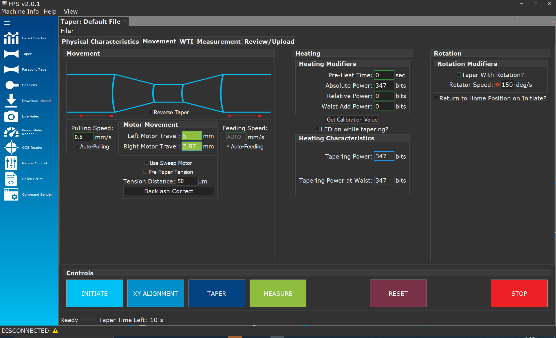
- Create, measure, and archive images of fiber tapers and ball lenses using FSM100 Fujikura fusion splicers and LZM series CO2 laser glass processor
- Write and optimize custom splice recipes in FPS and send them directly to the splicer with the click of a button.
- Easily create fiber taper geometry and set machine parameters for consistent results.
- Create fiber taper geometry and set parameters for consistent processes
- Graphical scripting tools for quick prototyping and debugging of unique fiber shapes
- Customize splice data collection for bulk splice data analysis
- Drive individual motors, manage the arc or lase, and regulate heat.
- Live video monitoring
- Mass uploading/downloading of splice modes into Excel templates
Les applications:
- Mise en forme
- Prototypage
- Effilage
- Collecte de données
Splicing in a research and development environment often requires tools not directly present in the splicer firmware or is time-consuming to access through the standard splicer menus. To address these needs, AFL developed the Fiber Processing Software (FPS) environment.
FPS is a PC-based system that expands the capabilities of the FSM-100 and LZM-100/125 series splicers. FPS is a unified application that gives users a variety of specialty splicing tools within one easy-to-navigate application.
Free & Powerful: AFL's Fiber Processing Software for FSM-100 and LZM-100/125 is completely free yet includes many powerful features. With a single software solution, you can access all splicer features and functions.
Modern UI: An easy-to-use interface with icon-driven navigation, layouts, full-screen modules, and dark/light modes makes operation quick and intuitive.
Easy Splice Recipe Creation: Write and optimize custom splice recipes in FPS and send them directly to the splicer with a click.
Component Fabrication: Create ball lenses, tapers, and parabolic tapers with an intuitive UI for refining parameters.
Live Auto-Data Collection: Automatically collect real-time splicer data in the background while controlling your splicer from your computer.
The Fiber Processing Software also includes a live video feed module, data zoom and navigation capabilities, interactive plots, and much more. Download now, and unlock the full potential of your FSM-100 or LZM-100/125 series splicer.
Fusionneuses ARCMasterreg FSM100M et FSM100P+,AFL PowerCleave,CT-114, CT-115 and CT-116 Fiber Cleavers,Coupe-fibres CT52,Coupe-fibres CT58,AutoCleaver NYFORS
2110