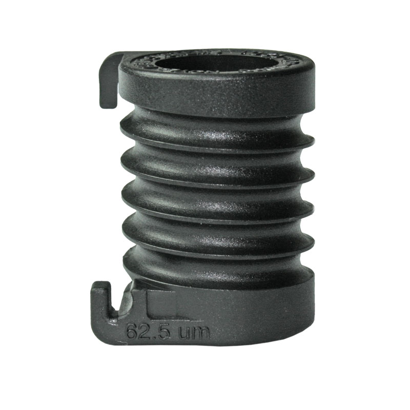
Para cumplir con los nuevos requisitos de fuentes de luz multimodo de la TIA/EIA-568-B, AFL ofrece mandriles para puentes de prueba de 50 y 62,5 µm con chaquetas de 3 mm. Ambos mandriles tienen ranuras para garantizar que los puentes se envuelvan exactamente cinco veces (como especifica la TIA/EIA-568-B) y pueden fijarse fácilmente a los puentes de prueba en segundos sin necesidad de herramientas ni cinta adhesiva.
3bae62a85569400cb1103acf7357eca6
1 Test & Inspection AFLglobal.com | 800.235.3423 Accessories Mandrels ©2020, AFL, all rights reserved. 5400-00-2001 Revision AD 2020-11-04 Specifications are subject to change without notice . For use with 62.5 and 50 μm Multimode Test J umpers with 3 mm J ackets Features • Allows existing 850/1300 nm LED light sources to test 50 and 62.5 μm links • Attaches to 3 mm jumpers in seconds, without tools or tape • May be reused indefinitely Applications • Required by TIA/EIA-568-B to measure attenuation on multimode fiber links • Certification of multimode links for Gigabit and 10 Gigabit Ethernet 62.5 μm 50 μm TIA/EIA-568-B specifies that attenuation (insertion loss) measurements of multimode fiber links, for all applications, must be made using an overfilled light source, such as an LED, with a mandrel-wrap mode filter on the transmit jumper. A key advantage of this specification is that it allows the use of existing overfilled LED light sources to certify both 50 and 62.5 μm fiber links for current and planned high bit rate applications including Gigabit Ethernet and 10 Gigabit Ethernet. To meet the new multimode light source requirements in TIA/EIA-568-B, we offer mandrels for 50 and 62.5 μm test jumpers with 3 mm jackets. Both mandrels have grooves to ensure that jumpers are wrapped exactly five times (as specified by TIA/EIA-568-B) and can be easily attached to test jumpers in seconds without tools or tape. Ordering Information DESCRIPTION AFL NO. Kit with two mandrels: 62.5 and 50 μm fiber 5400-00-0900 Mandrel, 62.5 μm fiber 5400-00-0201 Mandrel, 50 μm fiber 5400-00-0202
2 Test & Inspection AFLglobal.com | 800.235.3423 Accessories Mandrels Transmit jumper Mandrel wrap ST adapter cap Light Source Power Meter 0 dB Transmit jumper Mandrel wrap ST adapter cap 0 dB 0 dB Transmit jumper Mandrel 5 wraps Transmit jumper Mandrel 5 wraps 5 wraps Receive jumper ST adapter Cap ST adapter Transmit jumper Mandrel wrap 0.4 dB Receive jumper Receive jumper ST adapter Cap ST adapter Transmit jumper Mandrel wrap 0.4 dB 0.4 dB Link under test Transmit jumper Mandrel wrap Receive Jumper ST adapter cap ST ST 3.2 dB 3.2 dB 3.2 dB ©2020, AFL, all rights reserved. 5400-00-2001 Revision AD 2020-11-04 Specifications are subject to change without notice . For use with 62.5 and 50 μm Multimode Test Jumpers with 3 mm Jackets 1 Attach Mandrel Wrap the transmit jumper five times around the mandrel and attach it to the output port of the OLS 1 (LED source). Attach the ST adapter cap to the input port of the OPM 5 (optical power meter). Turn both units on and set wavelength to 850 nm. 2 Set Reference (One Jumper Method) Connect the output of the OLS 1 directly to the input (ST adapter cap) of the OPM 5. Then press and hold the Set Ref (set reference) key until the word “HELD” appears. When you release the Set Ref key the OPM 5 should display “0 dB” (+/- 0.05 dB) indicating that the power measured at output of the transmit jumper has been recorded as the reference level for your insertion loss measurements. 3 Check Jumpers Disconnect the transmit jumper from the OPM 5 (be sure NOT to remove the end of the jumper connected to the OLS 1). Attach the receive jumper to the OPM 5. Mate the free ends of the transmit and receive jumpers using the ST-ST adapter. Verify that the insertion loss of this mated connector pair is well under 0.75 dB, the maximum allowed by the TIA. Noyes recommends that the loss of your mated test jumpers be 0.4 dB. If not, clean both jumpers and repeat steps 2 and 3. 4 Test Links Connect the OLS 1 and OPM 5 to opposite ends of the first link to be tested. Store the insertion loss measured by the OPM 5 by pressing the STORE key. You can repeat Step 4 to measure the insertion loss of each multimode link at 850 nm. Then, if required, set both units to 1300 nm and repeat Steps 2 thru 4 to measure the insertion loss of your multimode links at 1300 nm. The OPM 5 can store insertion loss results at 850 and 1300 nm for up to 500 fibers. Example Procedure The following procedure illustrates how to make attenuation measurements of mul timode fiber links using an LED light source, optical power meter, and mandrels. The procedure assumes that the link under test is terminated by ST connectors at both ends. However, it can easily be adapted for links terminated by other connector types simply by using the appropriate test jumpers and adapter caps. For this procedure you will need the following: • (1) MM (LED) light source • (1) optical power meter • (1) ST adapter cap • (1) 62.5 or 50 μm mandrel • (2) test jumpers with 3 mm jackets and the same fiber type (62.5 or 50 μm) as the multimode link under test • (1) ST-ST (mating) adapter Contact Sales@AFLglobal.com to schedule a demonstration or learn how to buy. Visit www.AFLglobal.com/Test to learn more about mandrels. International Sales and Service Contact Information available at www.AFLglobal.com/Test/Contacts
Características:
- Los mandriles tienen ranuras para garantizar que los puentes se envuelvan exactamente cinco veces (como se especifica en TIA/EIA-568-B)
- Se acopla a los puentes de 3 mm en segundos, sin herramientas ni cinta adhesiva
- Permite que las fuentes de luz LED de 850/1300 nm existentes prueben los enlaces de 50 y 62,5 µm
- Puede reutilizarse indefinidamente
Aplicaciones:
- Requerido por la TIA/EIA-568-B para medir la atenuación en enlaces de fibra multimodo
- Permite la certificación de enlaces multimodo para Gigabit y 10 Gigabit Ethernet
- Permite que las fuentes de luz LED de 850/1300 nm existentes prueben los enlaces de 50 y 62,5 µm
- Puede reutilizarse indefinidamente
Mandriles para utilizar con puentes de prueba multimodo de 50 y 62,5 µm con cubiertas de 3 mm
La TIA/EIA-568-B especifica que las mediciones de atenuación (pérdida de inserción) de los enlaces de fibra multimodo para todas las aplicaciones deben realizarse utilizando una fuente de luz sobrecargada, como un LED, con un filtro de modo de envoltura de mandril en el puente de transmisión. Una de las principales ventajas de esta especificación es que permite utilizar las fuentes de luz LED sobrellenadas existentes para certificar enlaces de fibra de 50 y 62,5 µm para aplicaciones actuales y previstas de alta velocidad de bits, como Gigabit Ethernet y 10 Gigabit Ethernet.
Para cumplir los nuevos requisitos de las fuentes de luz multimodo de la TIA/EIA-568-B, ofrecemos mandriles para puentes de prueba de 50 y 62,5 µm con revestimiento de 3 mm. Ambos mandriles tienen ranuras para garantizar que los puentes se envuelvan exactamente cinco veces (como especifica la TIA/EIA-568-B) y pueden fijarse fácilmente a los puentes de prueba en segundos sin necesidad de herramientas ni cinta adhesiva.
Características
- Requerido por la TIA/EIA-568-B para medir la atenuación en enlaces de fibra multimodo
- Permite la certificación de enlaces multimodo para Gigabit y 10 Gigabit Ethernet
- Permite que las fuentes de luz LED de 850/1300 nm existentes prueben enlaces de 50 y 62,5µ
m - Se acopla a los puentes de 3 mm en segundos, sin herramientas ni cinta adhesiva
Información de pedido
| | DESCRIPCIÓN AFL NO. | | Kit con dos mandriles: Fibra de 62,5 y 50 µm | |
5400-00-0900PZ | | Mandril, fibra de 62,5 µm
| 5400-00-0201PZ | |
Mandril, fibra de 50 µ
m
5400-00-0202PZ
| 
Inspección de conectores multifibra óptica FOCIS Lightning2 | AFL EMEA España,Puntas de limpieza de conectores CCT – Limpieza de fibra óptica | AFL,Bastoncillos de limpieza de adaptadores CLETOP ACT – Limpieza de fibra óptica | AFL,Limpiador de conectores de fibra óptica Cletop | AFL,Limpiadores de conectores serie CLETOP Original – Limpieza de fibra óptica | AFL,Limpiador de conectores ópticos serie CLETOP-S | AFL,Limpiador de conectores y fluido de preparación mejorado FCC2, bote de 10 oz – Limpieza de fibra óptica | AFL,Limpiador de conectores y fluido de preparación de fórmula mejorada FCC2 – Limpieza de fibra óptica | AFL,Bolígrafo de limpieza de fibra FCC3 Debris Destroyer – Limpieza de fibra óptica | AFL,Kits portátiles de limpieza de conectores FCP – Limpieza de fibra óptica | AFL,Kits de limpieza de conectores FCP1 – Limpieza de fibra óptica | AFL
614