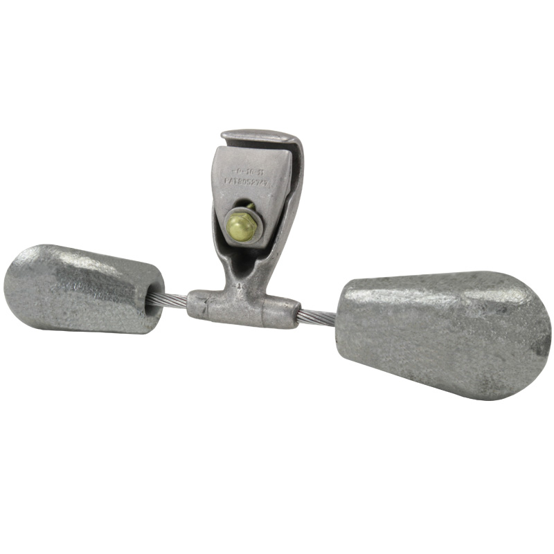
El nuevo amortiguador Dissipator 1700AA de alta eficiencia proporciona una mejora significativa en el rendimiento con respecto a nuestro amortiguador tradicional debido a su configuración única de peso en forma de campana. El nuevo diseño de peso compensado duplica el número de frecuencias resonantes, proporcionando así un rendimiento de eficiencia más consistente en el rango de frecuencias eólicas. Esta selección es para la compatibilidad de los conductores ACCC®.
1fbcd62ab59f460cb0daead450ca6727
18 Dissipator High-Efficiency Stockbridge Damper New Bell-shaped Weight Design AFL’s new Dissipator high-efficiency stockbridge damper 1700AA series provides a significant performance improvement over our traditional damper due to its unique offset bell-shaped weight configuration. The new offset weight design basically doubles the number of resonant frequencies, thereby providing a more consistent efficiency performance over the aeolian frequency span. AFL combined the proven performance of our unique bell-shaped weights and incorporated them in a design using two different size weights on unequal messenger lengths. The end result produced a damper with optimum performance that will eliminate damage caused by aeolian vibration thereby extending the life of a transmission line. VIBREC ® Damper Placement Software AFL has the longest standing history in vibration analysis today. From the many years of testing and gathering of empirical data, AFL introduced Vibrec, an integrated Windows ® -based vibration analysis program that is available as a “Free Download” on our website. This program allows users to perform analysis on transmission lines by inputting various mechanical and environmental parameters that can affect vibration. With this information, Vibrec determines how many AFL Stockbridge vibration dampers or Speed-Grip ® Spacers will be required for each span and suggests the best location for these accessories. You can also contact our technical support team for a free analysis. Features • Four natural frequency response modes and the unique weight shape provide one of the widest frequency ranges of coverage in the industry. • Damper’s unique bell shaped weight with smooth contours throughout the entire damper design provides corona performance up to 500 kV. • Optional break-a-way bolt available to ensure consistent torque requirements. • Special 19-strand messenger cable provides highly efficient energy dissipation. For more information, contact AFL's Technical Support at 1.800.866.7385. Unique conductor clamp design can be used on HiTemp ® conductor applications up to 250°C without the need for armor rods
19 Vibration Dampers for Aluminum Type Conductor (ACCC, ACSR, ACSR-TW, ACSS, ACSS-TW, AAC, AAAC, ACAR) Table 1: Weight Selection Table 2: Clamp Selection Ordering Instructions Notes: 1. Steel weight shown in Table 1 includes both damper weights and other steel parts used. For complete weight of damper assembly, add partial weights shown in Tables 1 and 2. 2. Regular aluminum hexagon head bolts are standard on assemblies that have 1705 weights and smaller. Assemblies having 1706AA weights and larger have special Corona hexagon head bolts. 3. For conductor sizes not covered in the table, consult AFL Technical Support Team at 1.800.866.7385. 4. Installation instructions for dampers start on page 393 of AFL's Transmission and Distribution catalog. 5. Weight combination sizes for cables smaller than 0.971” (1700 series) have identical weights on both sides. 6. Weight size 1701 uses a 7-strand messenger cable. Step 1: Determine Conductor Diameter All damper ordering is based on the diameter of the conductor being used. Step 2: Select Weight Catalog Number Use Table 1 to select the correct weight catalog number based on the diameter of the bare conductor being used. Step 3: Select Clamp Catalog Number Before selecting a Clamp, ask one question ‘Does this application require placement of clamp over armor rods?’ If yes, select the correct clamp catalog number from Table 2 based on the total diameter of the conductor and the armor rods. If no, select the correct clamp catalog number from Table 2 based on the diameter of the bare conductor being used. Step 4: Select Bolts For breakaway bolts, use ‘BA’. For standard bolts, leave blank. Step 5: Create Catalog Number Example: Without Armor Rods Conductor Diameter: 1.108" (28.1 mm) Weight Size from Table 1: 1706AA Clamp Size from Table 2: -10 Bolts: Breakaway Catalog Number: 1706AA-10BA With Armor Rods Conductor Diameter: 1.108" (28.1 mm) Weight Size from Table 1: 1706AA Diameter of Conductor and Armor Rods: 1.728" (43.9 mm) Clamp Size from table 2: -15 Bolts: Standard Catalog Number: 1706AA-15 Weight Catalog Number Clamp Catalog Number Bolts + + WEIGHT CATALOG NUMBER BARE CONDUCTOR DIAMETER RANGE WEIGHT 1 STEEL IN MM LBS KG ALUMINUM CONDUCTOR 1703 0.361 - 0.570 9.2 - 14.4 2.9 1.32 1704 0.571 - 0.770 14.5 - 19.5 6.5 2.95 1705 0.771 - 0.970 19.6 - 24.6 9.9 4.49 1706AA 0.971 - 1.210 24.7 - 30.7 8.2 3.72 1707AA 1.211 - 1.382 30.8 - 35.1 8.4 3.81 1708AA 1.383 - 1.825 35.2 - 46.4 16.7 7.57 CLAMP AFL NO. OVERALL DIAMETER RANGE AT POINT OF INSTALLATION CLAMP BOLT DIA 4 WEIGHT 2 ALUMINUM IN MM LBS KG -2 0.270 - 0.360 6.9 - 9.1 7/16 0.3 0.15 -3 0.361 - 0.460 9.2 - 11.6 7/16 0.3 0.15 -4 0.461 - 0.570 11.7 - 14.4 7/16 0.3 0.15 -5 0.571 - 0.675 14.5 - 17.1 7/16 0.4 0.16 -6 0.676 - 0.770 17.2 - 19.8 7/16 0.4 0.15 -7 0.771 - 0.870 19.6 - 22.1 1/2 0.6 0.26 -8 0.871 - 0.970 22.2 - 24.6 1/2 0.6 0.26 -9 3 0.971 - 1.090 24.7 - 27.6 1/2 1.1 0.50 -10 3 1.091 - 1.210 27.7 - 30.7 1/2 1.1 0.50 -11 3 1.211 - 1.330 30.8 - 33.7 1/2 1.1 0.50 -13 3 1.331 - 1.486 33.8 - 37.7 5/8 1.6 0.73 -14 3 1.487 - 1.643 37.8 - 41.7 5/8 1.5 0.68 -15 3 1.644 - 1.780 41.8 - 45.2 5/8 1.5 0.68 -16 3 1.781 - 1.960 45.3 - 49.7 5/8 2.2 1.00 -17 3 1.961 - 2.157 49.8 - 54.7 5/8 2.2 1.00 -18 3 2.158 - 2.375 54.8 - 60.3 5/8 2.4 1.09 -19 3 2.376 - 2.614 60.4 - 66.4 5/8 2.4 1.09
Características:
- Los cuatro modos de respuesta de frecuencia natural y la forma única del peso proporcionan uno de los rangos de frecuencia de cobertura más amplios del sector.
- El amortiguador’
tiene un peso único en forma de campana con contornos suaves a lo largo de todo el diseño del amortiguador y proporciona un rendimiento de corona de hasta 500 kV. - El diseño exclusivo de la pinza de conductor puede utilizarse en aplicaciones de conductor HiTemp®
hasta 250°C sin necesidad de varillas de blindaje. - Perno de ruptura opcional disponible para asegurar los requisitos de par de torsión consistentes.
Comealongs y HiTemp Comealongs para conductores ACSR AAC AAAC ACAR ACSS y ACSSTW,Compuesto de relleno de AFL,Compuesto para juntas eléctricas Alnox,Compuesto para juntas eléctricas Alnox,Compuesto de relleno HiTemp® AFL (AFCHT™),Compuesto universal HiTemp® AFL (HiTUC),Nº 2 Compuesto para juntas eléctricas,Terminales de compresión HiTemp® para conductores ACSS,Terminales de compresión HiTemp® para conductores ACSS/TW,Juntas de compresión HiTemp® para conductores ACSS,Juntas de compresión HiTemp® para conductores ACSS/TW,Puente de compresión HiTemp® para conductores ACSS/TW,Puente de compresión HiTemp® para conductores ACSS/TW,Manguito de reparación por compresión HiTemp® para conductores ACSS,Manguito de reparación por compresión HiTemp® para conductores ACSS/TW
1750
