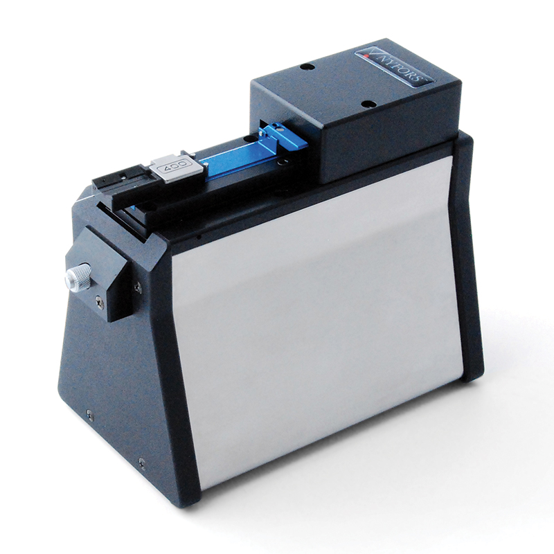
El CleaveMeter 3D es un interferómetro de Michelson con cambio de fase para la inspección sin contacto de la cara final de fibras ópticas cortadas y pulidas con diámetros de revestimiento de hasta 1200 ?m.
a54a5eeefb9d4c5f9fbb8f19d8d076d1
© 2013, AFL, all rights reserved. PP-4-00069, Revision 1, 3.23.16 Specifications are subject to change without notice. 23 23 Features • Full resolution surface reconstruction • 2D view of surface topography and pointwise slope • 3D view of surface topography with camera and lighting control • Extremely accurate, operator independent measurements of cleave angle and surface flatness over arbitrary diameters • Optional pass/fail indication of cleave angle for fast operation in production environments CleaveMeter 3D ™ The CleaveMeter 3D is a phase-shifting Michelson interferometer for non-contact end-face inspection of cleaved and polished optical fibers with cladding diameters up to 1200 μm. Designed for both production and research applications, this comprehensive fiber optic testing system combines full resolution, three-dimensional surface topography reconstruction and mapping with automated, operator independent measurements of cleave angle and surface flatness in a small, lightweight bench-top unit. When used in the 3D-mode, the surface topography is reconstructed from the fringe pattern and presented graphically as a three-dimensional image of the fiber end. By rotating the image and adjusting the scale and contrast, the surface quality and cleave angle at different points can be analyzed in close detail, allowing for a more comprehensive understanding and accurate interpretation of the data and the cleaving process. While this capability is always important to cleave quality analysis, it can be even especially helpful when analyzing cleaving of fibers with complicated structures such as polarization maintaining fibers, or micro-structured fibers. Information on surface topography can also be saved to a file for further analysis using third party software. Extremely accurate measurements of both cleave angle and surface flatness over arbitrary diameters can be performed on the reconstructed end-face surface. These measurements are carried out automatically, with full operator independence. This makes the system well suited not only for detailed cleave quality analysis in laboratory environments, but also for close production monitoring where software features such as optional pass/fail indication of cleave angle help ensure that consistent cleave quality is maintained over long periods of continuous cleaver operation. In addition to cleave angle measurements, the system can also be used to measure a number of other properties such as plane angles, fiber diameters and the distance between different points. The software allows the user to view the point-wise slope across the whole fiber end-face, a very useful tool for spotting small scale irregularities and crack propagation behavior. Adapter plates are available for both perpendicular and angled cleave analysis. The mechanical design is compatible with all NYFORS automatic fiber cleavers and accepts the fiber holders used with those machines as well as those of major splicer manufacturers. Custom made Adapter plates are available upon request. The CleaveMeter 3D comes in a small, ergonomic bench-top design and connects to the USB port of a PC running the host application. Reconstructed end-face surface of a cleaved 400 μm fiber (center cleave angle about 0.16°), with height scaled three hundred times to bring out surface irregularities and facilitate easier cleave quality analysis. Detail of above image, showing a dust particle or other surface contamination with a height of about 15 nm – illustrating the level of detail and sensitivity of the measurements.
© 2013, AFL, all rights reserved. PP-4-00069, Revision 1, 3.23.16 Specifications are subject to change without notice. 24 24 Specifications PARAMETER VALUE Fiber Cladding 125–1200 μm* Fiber Coating 250–1500 μm Camera Resolution 1280 × 1024 pixels Image Scale 1.25 μm per pixel Image File Format 8-bit JPEG, PNG, TIFF, BMP / 24-bit BMP for surface topography PC Connection USB 2.0 port Power Supply Through USB port Dimensions 97 mm (W) × 179 mm (D) × 142 mm (H) Weight 1.6 kg Absolute accuracy** 0.01° standard deviation Relative accuracy 5 % *Fiber-specific adapter plates required. ** This level of accuracy requires the adapter plate angle error to be measured and compensated for on each individual CleaveMeter ™ the holder is used with. For more information about system accuracy, please contact us at info@nyfors.com. Accessories DESCRIPTION AFL NO. Adapter Plates Adapter Plate, FJK, 115-210 μm 30100001 Adapter Plate, FJK, 200-529 μm 30100002 Adapter Plate, FJK, 510-800 μm 30100003 Adapter Plate, FJK, 800-1200 μm 30100004 Adapter Plate, NYFORS, Custom 30100007 Angle Adapter Plate, 15 degrees 30100008 Angle Adapter Plate, 8 degrees 30100009 Angle Adapter Plate, Custom 30100010 Fiber specific adapter plates are required to clamp and align the fiber to the interferometer optics. They are not included in delivery and should be ordered separately. Select Adapter Plate to match fiber cladding diameter and Angle Adapter Plate (optional) to match the fiber tilt angle. CleaveMeter 3D ™ Ordering Information DESCRIPTION AFL NO. CleaveMeter 3D includes: PC Software, USB Cable, Manual and Tools 30100013
Características:
- Reconstrucción de la superficie a plena resolución
- Vista en 2D de la topografía de la superficie y de la pendiente puntual
- Vista en 3D de la topografía de la superficie con control de cámara e iluminación
- Mediciones extremadamente precisas e independientes del operario del ángulo de hendidura y la planitud de la superficie en diámetros arbitrarios
- Indicación opcional de paso/no paso del ángulo de hendidura para un funcionamiento rápido en entornos de producción
Aplicaciones:
- Fabricación de componentes ópticos
- Verificación y prueba de cuchillas
El CleaveMeter 3D es un interferómetro de Michelson con cambio de fase para la inspección sin contacto
de fibras ópticas cortadas y pulidas con diámetros de revestimiento de hasta
hasta 1200 μm. Diseñado tanto para aplicaciones de producción como de investigación, este completo sistema de pruebas de fibra óptica combina la reconstrucción y el mapeo tridimensional de la topografía de la superficie con mediciones automatizadas, independientes del operador, del ángulo de hendidura y la planitud de la superficie en una unidad de sobremesa pequeña y ligera.
Cuando se utiliza en el modo 3D, la topografía de la superficie se reconstruye a partir del patrón de franjas
y se presenta gráficamente como una imagen tridimensional del extremo de la fibra.
Girando la imagen y ajustando la escala y el contraste, la calidad de la superficie y el ángulo de
calidad de la superficie y el ángulo de hendidura en distintos puntos, lo que permite
de los datos y del proceso de escisión.
proceso de corte. Si bien esta capacidad es siempre importante para el análisis de la calidad de la hendidura, puede ser
incluso especialmente útil cuando se analiza la hendidura de fibras con estructuras complicadas
, como
las fibras que mantienen la polarización o las fibras microestructuradas.
La información sobre la
topografíade la superficie también puede guardarse en un archivo para su posterior análisis mediante un software de terceros.
En la superficie reconstruida de la cara final se pueden realizar mediciones extremadamente precisas tanto del ángulo de hendidura como de la planitud de la superficie en diámetros arbitrarios. Estas mediciones se realizan automáticamente, con total independencia del operador. Esto hace que el sistema sea adecuado no sólo para el análisis detallado de la calidad de corte en entornos de laboratorio, sino también para la supervisión de la producción, donde las características del software, como la indicación opcional de pasa/no pasa del ángulo de corte, ayudan a garantizar que la calidad de corte se mantenga durante largos períodos de funcionamiento continuo de la cortadora.
Además de las mediciones de los ángulos de hendidura, el sistema también puede utilizarse para medir
otras propiedades, como los ángulos planos, los diámetros de las fibras y la distancia entre distintos puntos. El software permite al usuario ver la pendiente puntual en toda la cara del extremo de la fibra, una herramienta muy útil para detectar irregularidades a pequeña escala y el comportamiento de la propagación de la grieta.
Las placas adaptadoras están disponibles para el análisis de hendiduras perpendiculares y angulares.
El diseño mecánico es compatible con todas las cortadoras de fibra automáticas de NYFORS y acepta los soportes de fibra utilizados con esas máquinas, así como los de los principales fabricantes de empalmadoras. Las placas adaptadoras hechas a medida están disponibles bajo petición. El CleaveMeter 3D tiene un diseño pequeño y ergonómico de sobremesa y se conecta al puerto USB de un PC que ejecute la aplicación anfitriona.
Empalmadoras de fusión ARCMasterreg FSM100M y FSM100P+,Software de procesamiento de fibra FPS,AFL PowerCleave,CT-114, CT-115 and CT-116 Fiber Cleavers,Cuchilla de fibra CT52,Cuchilla de fibra CT58
2105
